ballen
Diamond
- Joined
- Sep 25, 2011
- Location
- Garbsen, Germany
Hi Mark,
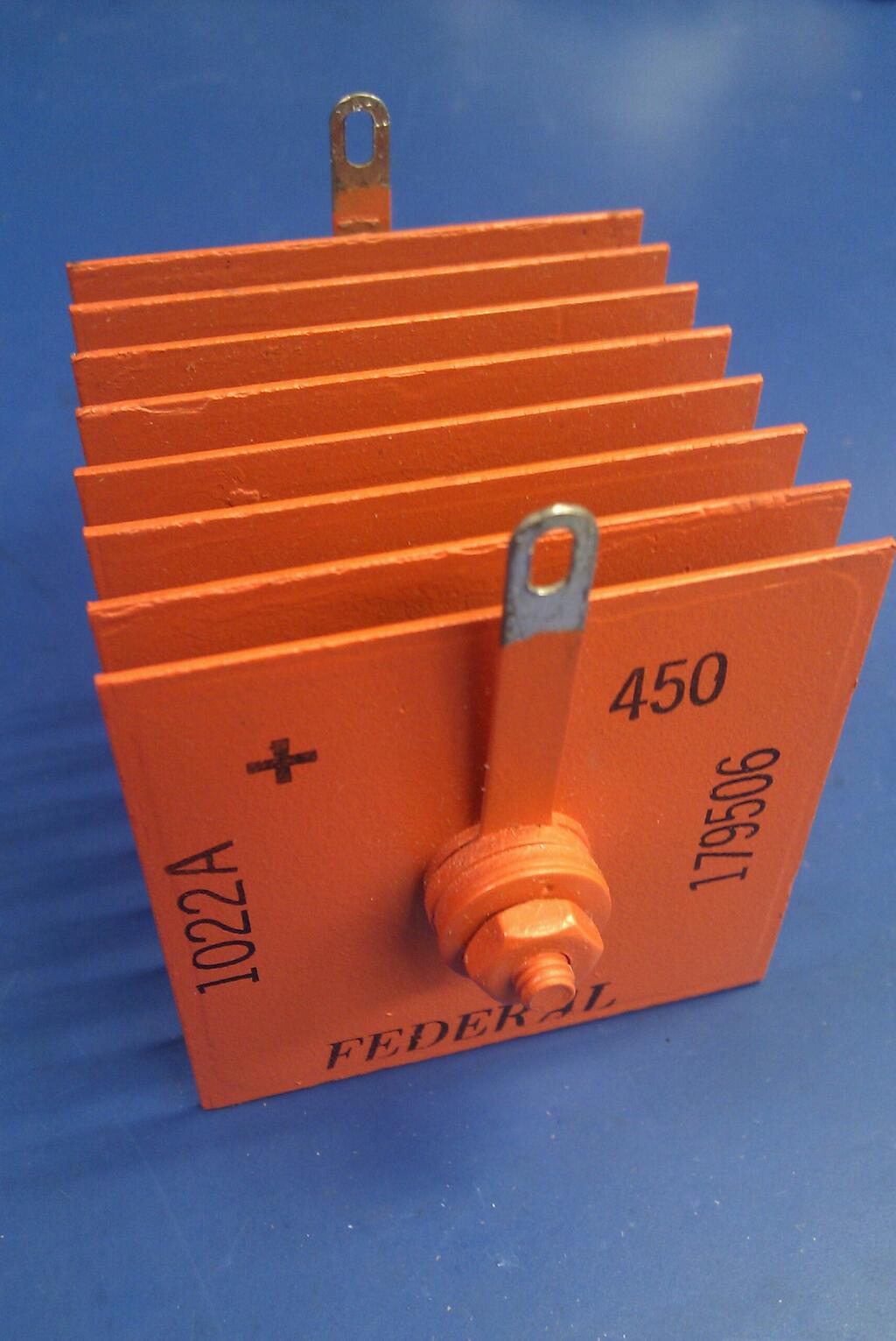
if a replacement rectifier is needed this is both easy and inexpensive.
Please confirm that when you wrote "the electromagnet works" what you mean is "when I connected the electromagnet in the brake to a benchtop power supply it worked correctly".
Could you remind me what electromagnet operating voltage was that you tested with? Was that value marked on the magnet or did you get it from the supplier of the brake?
Cheers,
Bruce


")


