What's new
What's new

Thermal Overload Troubleshooting/ID Help

G-ManBart

Cast Iron
Joined
Aug 17, 2016
Okay, this one is entirely on me, and now I'm looking for a bit of help. I'm far from an electrician, so I'll apologize in advance if I use a wrong term/description.

I've been working through evaluating my recent project lathe purchase (Clausing 6913) to see what's good, what needs to be fixed, etc. The machine was originally set for 460V and I have 230V from my RPC. The machine is configured with a single-phase F/N/R drum switch and a magnetic motor starter as well as a control transformer to provide the 120V for the drum switch. I reconfigured the motor leads and connections for 230V as well as the control transformer connections and fired up the RPC...everything seemed to work, but I only ran it for a short period of time. I just did the connections temporarily to make sure everything worked and the plan was/is to add lugs etc to the wires and clean things up.

My next step was to try the variable speed system and had the machine running when the overload tripped. I figured I did something wrong in the wiring so I checked the connections back to the RPC, reset the overload and it started back up. A few minutes later the overload tripped again (this should have been a clue). I pulled the cover off the mag starter box and started checking connections there. Reset the overload and it started up again....ran for a few minutes and tripped. At this point I remembered I hadn't even thought about the heaters in the thermal overload relays. Sure enough, the heaters were 4.5A and the motor draws 9A. Problem is, the overload relays won't reset now. I'm assuming the multiple resets so quickly damaged the melting alloy pot, or something similar. The heaters (marked H25) looked fine when I pulled them out to take a look...it should have H31.

Before I start pulling things apart I figured I would ask the experts. I also can't see any information on the exposed side of the OL relays to see if I can find replacements....might have to remove them for that.

If anybody can point me in the right direction on the OL relays to see if there's anything that might be repaired/replaced, and what model they might be, or if there's something that would be a direct replacement. Here are a couple of pics....the overall layout and closeup of the OL relays.

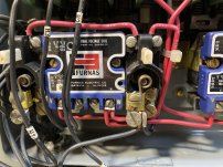
IMG_4203.JPGIMG_4204.JPG
 
Whats up with the control transformer, can you show the connections? Does it have a fuse protection? Your controls appear to setup for dual voltage operation, including the starter coils.

If the transformer fuse was sized for 480V and you ran it on 240V you could have blown the control fuse or damaged the transformer. Look into that first before tearing into the starter overload relay, but you still need the proper heaters.
 
A typical thing when changing voltage levels.
The original heaters are 1/2 the rating they should be when going from 408V to 240V.

The second pic with the top red wire. If that is an example of how wires are screwed then you should look over the whole rig.
Looking at this again, it's no big deal. Just do one wire at a time. Probably have enough slack to just rotate the ends of the wires
and reinstall. It's also neater to orientate the half-circle on the end of the wire to the rotation of the screw. Meaning that the end
of the wire is pointing in the direction of screw rotation. The screw will bite into the wire better.

Quick fix I never tried. Attach a wire across each heater connection. In theory each path will pass approx 1/2 the original current.
Would this be good for a final fix. No. Might be ok for a temporary run to get that last part finished.
Let's see how many want to tie me to the Whipping Post... Greg, please rescue me.
 
Last edited:
.......................

The second pic with the top red wire. If that is an example of how wires are screwed then you should look over the whole rig.

............................

Sheesh........... no kidding. First mistake... wires are tinned. Second mistake... wires are just stuck in "next to" the screw and are not even 100% under the screw.

Tinned wires will squash under the pressure of the screw, and become loose. If they heat up they may become looser, faster.

The wires should be left un-tinned, with the strands twisted to hold together

Wires should have both a "mechanical" retaining means and be tightened down (friction). Those have nothing but friction retaining them. If they loosen, nothing but chance and gravity is holding them in place. Others may have gravity pulling them out.

The wires should at least be formed to an "L" shape, preferably a "U" shape, so that they are at least somewhat trapped and will not come out if loose.

That can be hard to do with a "screw and plate" type connection, but that type connection is much more secure in the first place.
 
I have tinned wires and did it for the reason of getting frayed ends.
I have experienced problems with connections getting loose but I don't think I ever dealing with heat. Maybe not.
It might be better to just solder the end but that's not easy because the solder just wicks right up the strands.
 
Quick fix I never tried. Attach a wire across each heater connection. In theory each path will pass approx 1/2 the original current.
Would this be good for a final fix. No. Might be ok for a temporary run to get that last part finished.
The jumper wire and heater have to have the same resistance to split the current equally.

That said, in a real bind I'd use a jumper if just for a short time.
 
  • Like
Reactions: JST
If you were going to jumper something out, for troubleshooting, I would pick the overload control contacts, not the heater elements. Those elements are a pretty stout piece of material and can be easily removed, inspected and tested. His concern was the eutectic alloy mechanical portion not resetting. It would be better to test the overload control contact with a meter, than tear into the physical parts.

I never have seen one of those furnace heater elements or the overload relay go bad, after numerous trips. This is what makes me think he may hav lost control power instead of the overload block.

If the control transformer was fused , it may have blown from the voltage change, similar to the overloads not being changed. A fuse for a transformer that small would be a very small value and blow easily at a current twice its rated value. If there was no fuse the transformer could have given up.

Best to resolve these type issues with a meter if the poster is capable. Parts for Furnace controls sre not easy to come by, since they have been obsolete for several years now.
 
I have tinned wires and did it for the reason of getting frayed ends.
I have experienced problems with connections getting loose but I don't think I ever dealing with heat. Maybe not.
It might be better to just solder the end but that's not easy because the solder just wicks right up the strands.
If you look at the pics close up, the wires are tinned, or more accurately "solder soaked", all the way up the exposed part. Probably wicked up under the insulation too.

if it is a problem, a ferrule is a better idea than "tinning". No matter what, , a better job of trapping the wire under the screw is needed.
 
Whats up with the control transformer, can you show the connections? Does it have a fuse protection? Your controls appear to setup for dual voltage operation, including the starter coils.

If the transformer fuse was sized for 480V and you ran it on 240V you could have blown the control fuse or damaged the transformer. Look into that first before tearing into the starter overload relay, but you still need the proper heaters.
The control transformer does not have a fuse, but I did reconfigure the leads for 240V and confirmed I was getting the correct 120V out of it before I went any farther.

I found the problem, one of the relays didn't reset properly. I think I know how it happened, but can't be 100% certain. I had the box cover off and was looking at connections during the time the alloy would have been cooling, and pushed the reset buttons a few times. I suspect I may have done that at just the wrong time. When I opened up one of the relays the part that engages the spinning wheel was slightly twisted and popped free like it was hung up on a gear tooth.

I cleaned all the contact surfaces on both, reassembled the relays, reinstalled the relays, added power and bumped the F/N/R switch in both directions a couple of times and it powered up normally.

I have the correct heaters on the way and plan to clean up some of the wiring issues that have been mentioned. I actually mentioned that in the first post because I knew the eagle eyed folks would catch those errors!
 
Last edited:
A typical thing when changing voltage levels.
The original heaters are 1/2 the rating they should be when going from 408V to 240V.

The second pic with the top red wire. If that is an example of how wires are screwed then you should look over the whole rig.
Looking at this again, it's no big deal. Just do one wire at a time. Probably have enough slack to just rotate the ends of the wires
and reinstall. It's also neater to orientate the half-circle on the end of the wire to the rotation of the screw. Meaning that the end
of the wire is pointing in the direction of screw rotation. The screw will bite into the wire better.
I just posted that I found the source of the problem. I took apart both relays and when I opened up one of them, the part that engages the rotating wheel was twisted slightly and popped free like it was stuck. After the last trip I had the box cover off and was looking over connections and pushed the reset buttons a few times. All I can think is that I did that at just the wrong time and the one got hung up on the wheel as it was solidifying. I cleaned the contact surfaces on both, put them back together, reinstalled, added power and bumped the F/N/R switch a couple of times in both directions and it powered up like it should.

I have the correct heaters on the way.

The wiring issues you mention are what I was talking about in my first post when I said I was going to clean things up. When I work on stuff like this I try to imagine what the next person will think when they open it up, and I don't want them to think I was an idiot :-)
 
The wiring issues you mention are what I was talking about in my first post when I said I was going to clean things up. When I work on stuff like this I try to imagine what the next person will think when they open it up, and I don't want them to think I was an idiot :-)
With tinned wires it's not so bad. Why doesn't the connection have a straight wire method?
The smaller screws at V and W have a straight connection. I like those.
 
With tinned wires it's not so bad. Why doesn't the connection have a straight wire method?
The smaller screws at V and W have a straight connection. I like those.
No idea why only V and W are set up that way. I did a google image search on similar units and they all seem to be set up similarly for some reason.

I tend to prefer ring or spade terminals for this sort of application and that's I was thinking of doing for this.
 
The new heaters got here yesterday. I found an electric motor shop that sells parts on eBay and they had the amperage range listed. As best I can tell going off their packaging these are NOS Furnas parts and they had the amperage range listed.

Installed the new heaters, fired the lathe up and ran it for 30 minutes or so...zero issues.

Thanks for everyone who commented!


Back
Top