What's new
What's new

camshaft grinder

I assume it would be best if the grinder, lathe spindle and the follower wheel are all on the same center line
I cant see that it matters if the two spindles are level with each other. Just that the pivot is aprox 90º to the line between the two spindles, that may not even matter to much. To go to the extreme, if you have the cam directly above the grinding wheel, the pivot would be out in front of the vertical line between the two spindles and would rock you cam up and down. Same idea for the grind wheel to a little bit below cam centerline, the lathe would just be sitting on the grinder table at a slight angle. Then no trimming of lathe bed to keep the most mass (and john k happy). ;)
 
A very useful machine for a cam shop is a device to make a master from an existing cam .........this exactly like cheating off the best kid in class .....and is a winner .
 
Anything to do with grinding needs mass ,10x whats necessary for any other machining ........Lightweight machines etc will just drive you mad with chatter and vibration effects .
I'm sure you are correct but from my experience in machining a cam blank, way more chatter comes from the fact that the cam is so flimsy than the rigidity of the machine. I thought about maybe filling the lathe bed with sand or concrete or something similar. I'm sure I will need a steady rest or two. Our tractor cam is about 3' long.
I cant see that it matters if the two spindles are level with each other. Just that the pivot is aprox 90º to the line between the two spindles, that may not even matter to much. To go to the extreme, if you have the cam directly above the grinding wheel, the pivot would be out in front of the vertical line between the two spindles and would rock you cam up and down. Same idea for the grind wheel to a little bit below cam centerline, the lathe would just be sitting on the grinder table at a slight angle. Then no trimming of lathe bed to keep the most mass (and john k happy). ;)
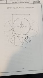
Here is a picture from the berco manual. It shows that the rocker action needs to be of equal distance each side of vertical.
 

Attachments

  • PXL_20230921_024018555.jpg
    PXL_20230921_024018555.jpg
    1.4 MB · Views: 8
Here is a picture from the berco manual. It shows that the rocker action needs to be of equal distance each side of vertical.
I agree that the tilt should be centered at half lift on the cam. At that half lift point as long as that line between the pivot and the half lift point of the cam is at 90º to the line between the cam centerline and grind wheel centerline you are doing the same thing. I am sure their machine is set up with both spindles at the same height up off the base so then you would set the pivot to be vertical in the center of it movement, I would think this is aprox 1/2 lift of the lobes. It is also 90º from the line of the spindles.
I just think it might be easier for you to just adjust the pivot to 90º using your existing plan rather than try to copy a berco or other machine exactly.
Think of it as putting a 1" spacer under the front of that berco machine so the whole thing is tilted back and the cam is 1" above the grind wheel center, the machine will still grind the same since the geometry relationship between the parts has not changed .
I see what you are saying and I believe you are right but it will still affect how much stock is removed when you dial in say .010" it wont actually take off .010"
 
This is why a Prince grinder would be superior.........the rocking pivot of the wheel is something like 30"-36" ,and the cam is rotated as on a normal cylindrical grinder ...........the heavy rocking mass of the subtable assembly would have to factored in to any machine of that type ...........considerable acceleration at lobes .....................on any kind of machine,steadies at every cam journal are essential.
 
Had you seen this video already?


Lots of details on how the grinder is set up and used.
Please note the master follower wheel here and it's size.
This is critical or the master cam needs to be a very weird shape. This of course can be done but .... not so easy.
Normally the master has an "envelope" or way oversized but the rise and fall are what matters.
Strange here to me is the cast or close to size starting stock for custom.
More used to a solid shaft that gets cut on a lathe and then milled flats on the 4 axis mill in the special world.
In big auto build yes you get cast to form.
Roller cams now have those internal curves so the mentioned stuff about wheel size can get in the way.
Acc/Dec ramps, inertia in the valve train.
Life of the valve springs? I have friends who throwaway valve springs every weekend or two.
Racing is fun.

Here is to our OP getting a national championship in his class with help from here. :cheers:
All this talk .. go do it any which way and see how she runs.
 
Last edited:
The boat guys next to me used to fit new springs every weekend ,the dumpster was always full of interesting stuff they threw away,just about every cam ever made ......they used to talk all kinds of engine BS all the time ......the guy who owned the shop fell at speed barefoot ski racing......he would have drowned if some people in a houseboat hadnt seen him go under .
 
The boat guys next to me used to fit new springs every weekend ,the dumpster was always full of interesting stuff they threw away,just about every cam ever made ......they used to talk all kinds of engine BS all the time ......the guy who owned the shop fell at speed barefoot ski racing......he would have drowned if some people in a houseboat hadnt seen him go under .

The Bridge to Bridge event is coming up in New Zealand soon, if you want to see a bat s*** crazy event, that's one of them

 
They used to go to a Murray River race ...cost was astronomical .....his buddies had a trucking co,they used to pull three semis and drivers off the road for three weeks to take all their stuff down to the race.............always come back with blown up engines ..........Although he used to sell some boats .......six or seven $50k boats a week in summer,and all the ski stuff............this is like twenty,thirty years ago........money was a lot more value then.....$50 k would have bought a house and land then.
 
This is why a Prince grinder would be superior.........the rocking pivot of the wheel is something like 30"-36" ,and the cam is rotated as on a normal cylindrical grinder ...........the heavy rocking mass of the subtable assembly would have to factored in to any machine of that type ...........considerable acceleration at lobes .....................on any kind of machine,steadies at every cam journal are essential.
I'm sure this grinder would be better but if it cost too much I may as well buy an actual cam grinder. I'm trying to keep the cost minimal. Also my shop is getting pretty full. I don't have room for something too large. Lol
 
Last edited:
Please note the master follower wheel here and it's size.
This is critical or the master cam needs to be a very weird shape. This of course can be done but .... not so easy.
Normally the master has an "envelope" or way oversized but the rise and fall are what matters.
Strange here to me is the cast or close to size starting stock for custom.
More used to a solid shaft that gets cut on a lathe and then milled flats on the 4 axis mill in the special world.
In big auto build yes you get cast to form.
Roller cams now have those internal curves so the mentioned stuff about wheel size can get in the way.
Acc/Dec ramps, inertia in the valve train.
Life of the valve springs? I have friends who throwaway valve springs every weekend or two.
Racing is fun.

Here is to our OP getting a national championship in his class with help from here. :cheers:
All this talk .. go do it any which way and see how she runs.
From what I read, the follower wheel needs to be the same size as the grinding wheel
 
Our tractor cam is about 3' long.

I've been biting my tongue not suggesting an old Hardinge second-op bed. Seems like it would be a good match for the app. And all the components are building block. However, the bed itself is only 36" long.

OTOH, they are easy to make from a block of steel. I've made sections of Hardinge split-beds to use the parts on other apps.

When it is all said and done, if you need a certain size bed and only one inverted V-way (think you said you milled the other off?) ; or like me, like the Hardinge headstocks and centers and such, it's not a major task to just machine a section of bed as long as you want from a bar of steel or Durabar.
Another method is to put the lathe bed features on a short stick, and cut it up to key onto a sub-rail of substantial section. My example is for a polishing and wood lathe. But it could instead be a shorter heavier solid section, like for a rocking table.

31" stick was made on mill & surface grinder, just cutting and squaring ends here.
DSCN3022.JPG

DSCN3030.JPG

smt
 
I only milled the 1 flat way. Its where the carriage fit. The ways for the tailstock are still there. I think this bed will work, I just have to keep the pillow block bearings up real close to the bed. It only needs to rock 1/2" or so. Our cam only has .375 lift at the cam. The rest of the lift is made up with the rocker arms.
 
Last edited:
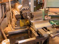
I did some tinkering and even with milling the back way off, the lathe bed is going to hit the grinder head before the the 7" wheel gets to the camshaft. I can lean the lathe bed back towards the wheel and that will help but it still needs more. I think I'm just going to put 10 wheels on it. I have some 10" wheels with a 3" hole. Not sure if I can buy a hub to fit the grinder that will take a 3" bore wheel. Definitely have to slow it down. I have the motor from this lathe that is 2hp I believe and I think it turns 1750 rpm. The cincinnati has 2 pulleys on the grinding spindle that are the same size and 2 on the motor that are differnt sizes to change the speed. I think I could make a new double pulley that are both the same size and run 2 belts. Not sure even 2hp is enough to run a 10" wheel


Back
Top