What's new
What's new

Help! Trying to grind large spherical radius on small part.. Maybe need CNC grinder..

It is just under a .003 rise which is a goodly amount. A cup wheel twisted to the rotation axis can do this but will not be a true arc.
It becomes a spline and more important not in the OP's equipment capability.
 
Hi All:
I modeled up the feature in CAD just to see what the OP is up against.
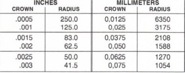
The height of the dome is only 0.00273" over an 0.875" diameter.

To get this feature accurate is not a job for some hokey setup on a 1950's beater cylindrical grinder.
Carbide Bob got it right when he remarked that you need to control tenths to make this anything more than wishful thinking.

If you try to form the shape on an aluminum oxide wheel by any method, your error is going to significantly influence your outcome.
I don't think you'll get there with a form wheel.
If you just form dress the side of a wheel and then drive it into your spinning workpiece the ridges you make will likely be 50% of the height of the profile.

I don't think you will win unless you generate the radius with the periphery of a flat faced wheel.
I'll bet something like a CNC cutter grinder could do this accurately enough to be worthwhile, so I'd contact Alfred Lyon at AB tools and see if he can run something like this for you on his Anca grinders..

If that is unappealing, I'd just turn it on a CNC lathe and accept what I get.
Unless the OP is trying to machine some crazy exotic ceramic or something, a fine turned finish will probably be better than some bodged grinder hackup.
There are vendors out there who claim to be able to hard turn to microns...find one and let them go at it.

If you just can't resist, I'd find a way to swing a toolpost grinder on a lathe or cylindrical grinder...you'd have to build a godawful swing arm contraption over the headstock end and you'd have to build it like a brick shithouse, but you might have a stab at it.
You could also swing a headstock with your workpiece in it past a stationary grinding wheel; a Sherline lathe headstock with a tiny 4 jaw chuck is small enough to mount on a swing arm and is self contained and motorized too.
All you'd have to do is build it onto a swing arm and then set it up on a Bridgeport so the Bridgeport spindle carries the grinding wheel and the table functions as a place to mount the swing arm, or set it up on a cutter grinder like a Cincinatti and do the same thing.
But I wouldn't personally waste my time on such a kludge...I'd farm it out.

Cheers

Marcus
Implant Mechanix • Design & Innovation > HOME
Vancouver Wire EDM -- Wire EDM Machining
 
For one part at a time "on a "lathe" type machine.

A swinging link between work headstock and a carriage could define motion as the "cutter" translates across the spinning work.

The link of course being the same length as the desired radius "pin to pin".


There also is always the possibility of following a template.
 
Door lock pins for a martian lander.
I will have to go out to the shed and check to see if my lander's door hatch has a 35" radius, and the pins are a dead match.

We should know the tolerance limits before suggesting buying expensive new equipment..a grinder as simple as a Royal Oak would make fast easy work of a +- .001 35" radius.

I could make a swing arm dresser for my Cincy #2 and run such a part to .001..Having a type 1 wheel, likely a 60 grit, with the wheel head tuned to 90 ..in line with long travel. coming to my stop and using the screw solid stop as the infeed device for .006 /,008 infeed to clean-up..running the part in my Cincy work head.

Yes, could do the same with a roll-dresser and a crush wheel, but that would be overkill.

Yes would have to know the length of the part, before suggesting a Cincy #2.
 
I told this story elsewhere, but it's applicable here.

I had one of those not too long ago. This may be a long one... About a 50" radius on the end of a 3.500" diameter pin. The 50" R was a two place decimal, so +/-.010" for this particular customer. No big deal, except that the shape of the spherical curve near the center of the radius doesn't change much at ALL with even a .020" R change when you're talking a 50" R. From one end of the tolerance to the other we're talking the spherical shape changing by tenths across the curve. Location of the end wasn't tight in this case but the shape of the spherical end was! The guy who quoted the job didn't understand that part.
I used the readouts and a button tool to generate the radius, and then it was to be chrome plated. I warned him about that affecting the radius too - that the chrome would build heavy near the corners and edges of the part and it might get bounced at inspection if he's not real careful. So they get it back and polish the chrome a bit and send it to the customer. It gets bounced. Radius is perfect in the middle but no good near the edges. Too flat, bulged out from the chrome. I tell him get it radiused, chrome plate it, then send it for grinding. He does that, now it's looking perfect. It gets sent to the customer.

I go with this time, to see what they're inspecting it with. The inspection guy boots up a 5 foot long Faro arm. I'm already skeptical but I keep quiet. They check the radius by building a point cloud. He punches a button and the machine pronounces it spherical within .0004" and within tolerance for the radius. Great. I ask him, "Just for giggles, do it again, would you?" So he does. This time it's out .0014". The next time .0023". Then it's back to .0002". The calculated radius has varied by something like .050" between all these. I ask, "What's the claimed accuracy on your arm there?" He says "Oh it's pretty good, something like +/-.001"."

*Forehead slap.*


So yeah, if that radius needs to be close, you'll need to hold it very tight. The application on this particular pin was as a thrust surface against a concave radiused part, so they wanted it very close to the correct shape.

Edit: forgot to mention it was subbed out to a CNC grinder.
 
Last edited:
Oh and no, actual automotive tappet grinders like a sunnen or old Tobin-arp leave horrendous finishes, and really don't grind a true spherical radius, already been down that road..
The Sunnen and Tobin Arp machines DO grind a spherical. I have seen traces of lifters ground on a Sunnen and they were given a thumbs up by TRW engineers. You will get a good finish if you have the correct stone, coolant and dress on the wheel.

For true; our OP made an incorrect assertion based upon an encounter with either an incorrectly set up machine, an incorrect grit wheel or incorrectly dressed wheel.

The Webb/Tobin-Arp/Sunnen tappet grinders have reconditioned millions of lifters and returned them to service.

jack vines
 
It is just under a .003 rise which is a goodly amount. A cup wheel twisted to the rotation axis can do this but will not be a true arc.
It becomes a spline and more important not in the OP's equipment capability.

The magic is in the dresser it swings to put a concave radius in the wheel.
 
Hi gapppmast:
Yeah that's true, but if you're using a dresser anyway to form the radius...why would you do it on a cup wheel?
I thought the whole idea was to angle the cup wheel so you could fake the radius without having to dress it.
DId I misunderstand something somewhere?

Cheers

Marcus
Implant Mechanix • Design & Innovation > HOME
Vancouver Wire EDM -- Wire EDM Machining

If you "fake" a radius you have a cone which would cause camshaft failure. The tappet grinder was based off a valve grinder design which used a cup wheel. The reason a cup wheel was used for this application is the surface speed remains constant though out the life of the wheel.
 
Running dressed in the OD of a type 1 wheel would give a true Radius related to the constant diameter and likely a better finish than the canted cup wheel. Most any grinder would do nicely..like a surface grinder, OD grinder or TC grinder....with having a way to rotate the part.

The canted wheel would be best served with a straight-sided cup wheel having the OD trued up and dished to about a 1/8 cutting area. Likely a 60 grit or so would be oK. ..also having a way to rotate the part.

Needing perfect concentricity and with having a pre-done at tenths diameter the holder hole/bore might be ID ground in place
 
The dressing arm does not pivot on a 50" or other long arm. Instead it is set on a compound angle to the spindle shaft. One of the angles is adjustable to give a different crown from .0005" to .003" based on a 1" diameter lifter. The concept does work I have seen traces and it is a true radius.
 

Attachments

  • Radius chart.jpg
    Radius chart.jpg
    22.3 KB · Views: 28
  • dresser1.jpg
    dresser1.jpg
    8.8 KB · Views: 34
  • Dresser2.jpg
    Dresser2.jpg
    10.2 KB · Views: 29
I would likely set a diamond at the end of a long bar and have a hole for a stripper bolt at center line 35" away at the opposite end if running with a type 1 straight wheel, with the diamond set screw verticle so as to not change the diamond center position....anf=d find the crossfeed number that makes cross-wheel center lin, and mark that number on the prion or on the bar.
Plus adding a block of sorts to make wheel center height position.


Back
Top