michiganbuck
Diamond
- Joined
- Jun 28, 2012
- Location
- Mt Clemens, Michigan 48035
I think those numbers are darn chose for a lathe
(reading every 8": (converted from mm so the numbers are a little strange)
(0 / 0 / +.00025 / +.00037 / +.0005 / +.00037 / +.00037 / +.0005 / +.00025 / 0 )
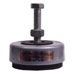
I would let it rest for a long time, and then if still out ..00025 I would make a center foot and jack it up .00025 (or what).
(reading every 8": (converted from mm so the numbers are a little strange)
(0 / 0 / +.00025 / +.00037 / +.0005 / +.00037 / +.00037 / +.0005 / +.00025 / 0 )
I would let it rest for a long time, and then if still out ..00025 I would make a center foot and jack it up .00025 (or what).
") )
)
 )
)