What's new
What's new

Requesting Recommendations for a Robust Goose-neck Clamp Lamp

It's one of their uses but they offer it for other purposes like in the link. The OP could make a setup using 3/4"
Yes, I could make a setup from raw materials to hold the heaters. But I'd much rather buy off the shelf a robust positioning device that has a base clamp, adjusting mechanism, and mounting stud already assembled and ready to go. Afterall, 3 feet of 3/4" LocLine would cost as much as the entire rig I ordered. Ant then there is a base clamp to source and adapt to the line and the same concerning the mounting of the heater on the other end. It is not a question of ability to make an eventually working device. It's more that the time involved in designing and making a more or less workable prototype and then the fiddling to make the prototype actually work well is more than I'd like to invest.

Denis
 
i just bought 10 of these. $1 per piece, incl. 14 day delivery. you never know when you need them and they are disposaable, like for welding.
 
Could you use a heat mat under the work? Throw a blanket or box over all to capture heat until it warms up. When I pull iron out of degreasing tank I will dry it off with a propane torch so it does not rust. Just wave it over very fast from several inches away. You can see it dry off
I have a golden rod heater under my lathe to stop condensation in winter. I put a heated pad inside the base of my mill for the same heating effect. I control both with one thermostat set to come on at 47 degrees inside the shop. I get condensation at 45 degrees or less. It only runs a few days a year in my climate.
Bill D

I have used a heat blanket but it is not convenient/workable due to positioning requirements while heat is applied. The heat emitters work great as long as I can get them into position. The positioner linked by me above comes tomorrow. I’ll report how it works.

Denis
 
I got the positioner linked by SFriedberg
1698987967413.png
I can confirm that al the parts are aluminum including the pink locking handles, tubes, ball ends, and clamps. The unit will support far more than .5 pounds. I think it will be ideal for my particular needs and will offer a fair bit of flexibility. That said, it does lack the rock-solid rigidity you might like in the connection of the arm to the clamp so it would not be ideal for such things as dial indicators and other precision setups. But for holding my heat emitters or for lights, microphones and similar jobs it is well-suited.

I will be picking up one or two more.
I will try to post what I make to hold the emitters. I would like a bank of three emitters. So, I will need three arms.

Denis
 
Some follow-up on this request:
I 3D-printed in PETG an adaptor allowing convenient attachment of a ceramic base to the arm. The adaptor has a channel allowing feeding a lamp cord up through the adaptor and into the ceramic base into which the emitter screws.

This is the ceramic base I used:
1699335008060.png

Here is the arm extended more than it likely ever will be in actual practical use. It has no trouble supporting the emitter that is screwed into the base which is held in place by the adaptor.
Pic4.JPG

You can see there is a brass pin in the arm head that registers with the adaptor and prevents rotation.
Pic3.JPG
I passed a single wire to illustrate the electrical line passage in the adaptor.
Pic2.JPG

When I install the lamp cord, I'll just zip tie to the arm.
Pic1.JPG
Here is the CAD drawing. The threads are 3/8-27 to match lamp nipples. Incidentally, no chasing of threads was necessary. The parts screwed together with threads as printed.
1699334374098.png

Here is a cross-sectional view showing the electical cord passage in the adaptor. The lower internal thread is 1/4-20.
1699334477570.png

On order are two more arms and emitters.

Thank you to everyone who contributed ideas.

Denis
 

Attachments

  • Pic2.JPG
    Pic2.JPG
    242.7 KB · Views: 1
Denis, the first time you use this, you might monitor the temperature of that metal flange to see it stays well below the softening temperature of your PETG filament material. Under 185F should be safe, although it might be a bit weaker at that temperature. Thinking of the pipe-threaded spigot here...
 
Denis, the first time you use this, you might monitor the temperature of that metal flange to see it stays well below the softening temperature of your PETG filament material. Under 185F should be safe, although it might be a bit weaker at that temperature. Thinking of the pipe-threaded spigot here...
That is a very real consideration. Before drawing and printing the part, I plugged the emitter in for few hours and noted the base of the emitter itself got to about 120F---you could hold your hand on it though it felt distinctly hot. The ceramic base is much cooler. I may redraw the adaptor and replace the spigot with a female threaded hole and screw in a standard metal lamp nipple as I think that would be a ruggeder design. I will likely refine the geometry a bit making the 1/4-20 hole a shade shallower, move the wire passage down a bit and thus allow a deeper hole for the nipple.

Denis
 
I did revise the adaptor eliminating the spigot which was a potential weak spot. It has not yet failed, but I think that was likely to occur at some point. I also widened the portal for the power cord.

1699409115838.png

1699409211800.png

1699409462918.png

A 3/4" length of lamp pipe nipple will be threaded into the big end and will replace the plastic spigot.

Denis
 
One unit is assembled as I wait for two more adjustable arms. I used medium-weight lamp cords (the heaters are 150 watts) and passed the wire through the 3-D printed adaptors and the lamp nipple pipe and wired the ceramic bases and then screwed them down onto the adaptors. Then adaptors were screwed into the arms and the wires attached to the arms with a few zip ties. (The cut ends of the ties were melted and smashed with a hot piece of bar to prevent sharp ends of the ties from snagging hands and arms later when in use.)

The gang of three arms/emitters will clamp individually as needed or as a group to a 1X1 square tube when needed and all three will be plugged into a three-outlet cord which will be attached to the tube. All-in-all I tried to make a solid and convenient assembly.

Here is one of the arms assembled:Emitter5.JPG

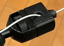
Here is a close-up of the adaptor with the wire strung through it into the base. Earlier I indicated the attachemnt had a little looseness, but since using the provided holes for a tommy-bar and snugging the arm clamp to the adaptor well, the attachment is rock-solid. With the lamp nipple as an attachment device that joint is also very strong where the original spigot was a potential weak point.
Emitter6.JPG

Here is a single heater configured in a typical way for actual practical use.
Emitter8.JPG

If, on the outside chance, anyone wanted to use the .stl file I made to print their own adaptor, I'd be happy to share it. It is, of course, not that hard to draw, but it does have a few tweaks to compensate for expected shrinkage of the PETG part so that the pipe nipple and 1/4-20 clamping bolt fits ideally.

This piece goes to work right now as I have some epoxy to apply and cure on a pattern and I want to speed it up.

Denis
 
Last edited:


Back
Top