What's new
What's new

Leblond 14 inch tool and die maker

58-66cadilac

Plastic
Joined
Apr 29, 2013
Location
Logandale NV
So, I got a pretty good deal on this LeBlond 14 inch T&D maker; sn# 6HC355; circa 1968; servo shift. That being said, it was not under power when I did the deal, and the fellow I got it from didn't know much about it's history nor Lathes. He picked it up from a fellow out of California who had picked it from his work. Apparently, it was in a production shop to perform a certain task, but the motor went bad so the production shop sent it home with the first fellow.

I've straighten out a few handles that were broke. I have filled the head stock and apron with oil, replaced the ZSS brushes, and finally installed the motor that was provided with the lathe.

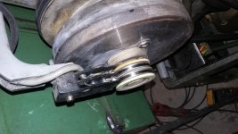
I seem to either have the wrong belts or the wrong pulley on the motor. I have frame 213T, I think 215 is the stock motor frame, but they are dimensionally equal from what I can tell, just HP rating is different. my motor pulley is 5 inches in diameter and the belts are 3v710.

If anyone has a tool and die maker, can you send me a pic/deminsions of the motor pulley? I have manual# 3907, it isn't the exact book, but another 90$ to LeBlond right not can't happen until after Christmas. I can turn this pulley down to size, if it is the wrong one, I am just trying to get it working to see if I am going broke saving money....again. LOL George20171213_185630.jpg20171213_185650.jpg
 
Thanks! I now have the correct pulley on the motor.

I haven't got it fully working. I am able to turn the spindle motor on but the clutch wont engage nor the hydraulic pump to work. When I select a new speed there is a solenoid in the power box clicking, but it wont "wobble" the main shaft to engage the new speed.

I am going to search around here to try to understand how the servo shift vs clutch works. I have the copy of "my break wont work" from LeBlond though if I get there! some day.

I have the schematic but unfortunately there have been some folks showing their knowledge of electrical workings in the machine. Several wires have been repurposed and redirected. I'll need to make my own custom schematic.

can you point out which one of these is the zero speed switch and what the other is?20171225_220454.jpg 20171225_220502.jpg
 
Awesome! I am starting to understand this a little. So the zero speed switch (ZSS) was originally a mercury switch at the extreme end of the clutch/ brake shaft. This ZSS is connected through the brushes with the white ring. If the spindle is turning the mercury falls away from the contacts and registers open. This mercury switch is no longer available and has been replaced with an electronic monitor circuit (380$ from LeBlond Dec 2017). It is possible to just bypass the ZSS with a push button and save the 380$ for a new tool!

The clutch as I understand it is operated through the Dynamatic brush assembly. I do see a set of wires going from the Dynamatic brush set commutator through the belt pulley to a set of terminals on the magnetic coil of the clutch, this is most likely the clutch engagement magnet, similar to an A/C clutch on a car.

So the Dynamatic brush assm is for the clutch then where is the brake? 20171228_223012.jpg Is it behind the pulley against the head stock housing?20171228_222928.jpg. I am supposed to check brake operation before tackling the oscillation problem, I wonder if in the brake setting (Down position of the lever that operates brake and oscillation) am I supposed to be able to turn the Spindle?

I will be out checking some voltages/ continuity to these brush sets. I would like to just understand the locations of the brake and the clutch mechanisms.
V/R
Geo
 
Last edited:
Thanks! I appreciate the help.

I think I can say I have read every post on PM with the tag "servo shift"! I see a variety of issues with them. Seems people love hydraulic shift, or hate them. My nearly free lathe is a bit of a basket case, but it seems to be in good shape. I am "electric" smart, but undoing the previous folks trickery is a bit annoying. I also like to fix things the correct way, obviously not everyone can do this.

One nice thing I did learn is servo shift appears to be the same for Regal lathes as the T&D lathes. Also, I've got to know the folks over at LeBlond by first name! Awesome support for such an old product. They are great at answering questions for a guy who didn't spend any real money with them.

I will try to summarize this issue and operation once I get it figures out. I am surely not the last guy to take in a Servo-shift issue. Understanding how the lathe works is hard with a inoperable machine. Knowing what right looks like is key.

Cause we all like pictures, here is a pic of the machine.
Geo20171121_202729.jpg
 
Well if anyone cares I finally got back around to this lathe today and got'r figured out. I had inherited a little bit of a rat's nest! But I got the wires going to the correct terminal and viola! she works well! I do need to tear the hydraulic plate apart in the head stock, as it is off one tooth. I will spend the next few months working the electrical tubing and re-wiring the machine to give it some decent serviceability once I start running it. I am ditching the RPC I am running now, for a VFD. I don't want to work out the tuning issue with the rotary and L3 running at 280 Vrms!. Anyone been into the headstock on one? I have a little noise in one gear so I should look into the gear sets for issues.
 
Last edited:
Your lathe isn't as good of a candidate for a VFD as you hope. As I understand them, VFD's don't like to have their load disconnected. And that is exactly how your LeBlond shifts gears. You need the apron lever to turn off the drive motor, and then turn on the much smaller hydraulic motor to change gears. And then you have the electric brake load. I think a RPC would be a simpler choice.
 
The 14 inch Tool & Diemaker is a bit different than the typical LeBlond Regal lathe, in that the drive motor runs continuously after startup.

An electric clutch disengages the drive motor from the spindle mechanical components during the brake/hydraulic motor Servo Shift cycle, while the drive motor continues to run.

I'm not a VFD expert, but in this case wouldn't the load remain connected?

Mike
 
I think your correct Mike, The VFD will always have the spindle motor running, When I shift gears it runs the hydraulic pump and the "wiggle" gear train (Dual shaft motor). The amp on the hydraulic/wiggle motor is like 5 amps max.

I have read up on the "tuning and RPC" and the thought of buying cap's until I get the load balanced out just isn't enticing at all. I am barrowing a LARGE RPC right now, as mine is 7.5 HP and the motor on the LeBlond was upgraded to 7.5 HP from 5 HP. So I guess I could re-power back to the 5 HP and run the 7.5 RPC if I have to. I am new to VFD's so I need to play with them some more. I just re-powered my Bridgeport Clone to a VFD. It was pretty straight forward (So Far).

I had half a mind to replace both motor contactors in the LeBlond with two VFD's and use the logic bus to run low powered controls to run the lathe.

I have few Irons in the fire so I got some time to figure out the best way to go. I need to get into the Servo-shift mechanism as the plate is a tooth off and the dial does not match the speed. I also have one gear making A lot of noise!
 
I did some (very Little) reading today in my VFD booklet. It states only restive or inductive loads such as motors and heaters can be hooked up to it. There is a transformer in the control box to provide DC volts to the brake and clutch. I am thinking you might be on to something here. I will have to read some more but the contactors and transformers may have an issue with the VFD as the resistive load? I think what your saying is if I don't have the motor running the transformer wont work? which wont allow me to control the Servo Shift pump/ brake.
 
Your lathe isn't as good of a candidate for a VFD as you hope. As I understand them, VFD's don't like to have their load disconnected. And that is exactly how your LeBlond shifts gears. You need the apron lever to turn off the drive motor, and then turn on the much smaller hydraulic motor to change gears. And then you have the electric brake load. I think a RPC would be a simpler choice.

I did some (very Little) reading today in my VFD booklet. It states only restive or inductive loads such as motors and heaters can be hooked up to it. There is a transformer in the control box to provide DC volts to the brake and clutch. I am thinking you might be on to something here. I will have to read some more but the contactors and transformers may have an issue with the VFD as the resistive load? I think what your saying is if I don't have the motor running the transformer wont work? which wont allow me to control the Servo Shift pump/ brake.
 
Can't believe I found someone working on a 14" tool and die. I am doing the same. mine was working fine all of a sudden I cant get voltage to the clutch. any help is appreciated. Alex
 
For multiple motors and multiple other controls, an RPC is far better than a VFD. VFD works well for one motor where it is switched on and off via the VFD. I have 440v three phase VFDs on the feed motors of a mill running off a balanced RPC and a step-up transformer... can't do that with a VFD. Balancing the RPC is really not that bad. You can use HVAC compressor/fan capacitors for more variety. The three lugs can be jumpered to give you three different values (say a 35/5 will give you 35Mf, 5Mf or 40Mfm depending on how you jump). It took me about four hours to get mine tweaked 13 years ago and I have just run it since.

As for RPC capacity, your 7.5hp RPC should run that lathe fine, as it doesn't start the motor under load. One of the great advantages to clutched lathes, they are much easier on motors and switch gear. I have been running my 5hp L&S off a 5hp converter again for 13years. As long is it is just the motor starting, it doesn't require the usual 1 1/2 times capacity.
 
Can't believe I found someone working on a 14" tool and die. I am doing the same. mine was working fine all of a sudden I cant get voltage to the clutch. any help is appreciated. Alex

Well Do you have the schematic? I would say start with the brushes if you know you have the 90 (I think) VDC. To operate the clutch it's pretty in depth(not impossible). What year is the lathe?

power flows through the transformer to a rectifier bridge then the interlock between brake and clutch is accomplished with a large relay. The relay/interlock is controlled with AC voltage. The DC voltage from the rectifier will flow through one of the two AC voltage controlled two contactors that then power either the clutch or the brake VIA the rheostats. The clutch has a set of 4 brushes that feeds it through the motor shaft.


Does your lathe have the zero speed switch still or has it been converted? I have my ZSS bypassed. I haven't yet determined if it's good or bad do to the crazy voltage imbalance I have on L3.
 
Last edited:
Thanks so much for the reply. I do not have a schematic I know it is ninety volts a still has the 0 speed switch. no power at either brush assy. When I move the lever to brake I can here it trying to shift. When I move the lever to the up/on position I can hear a contact in the wiring panel?
Thanks, Alex
 
Id hit up Leblond for EE314 I think. You can PM me I can send the one I got from them. No voltage at either brush leads me to believe either the Shift switch or a bad contactor. So it's not engaging (spinning) the spindle but the spindle motor is running and it shift speeds fine?
 
Thanks so much for the reply. I do not have a schematic I know it is ninety volts a still has the 0 speed switch. no power at either brush assy. When I move the lever to brake I can here it trying to shift. When I move the lever to the up/on position I can hear a contact in the wiring panel?
Thanks, Alex

Sorry I worked all weekend, I didn't have time to get on the web.


Back
Top