What's new
What's new

Full tear down and Rebuild of a 10EE Round Dial

The goal is to identify the correct windings to be paired from the two sets of three-phase windings. I will call the two sets 123 and 789. These two windings should be separable. You do not show them connected at the center of the star.

First connect 120 volts between windings 1 and 2 and put your light bulb in series to limit the current. Measure the voltage between all combinations on 789. One reading should be close to the reading between 1 and 2. If your numbering is correct, you will get a similar reading between 7 and 8. Now connect lead 1 to lead 7. Do not connect 2 to 8 but read the voltage between 2 and 8. It should be very low. Do this for the other coils in 123.

What we are doing here is using the fact that the 123 windings are parallel to the 789 windings. As such, the motor will act as a transformer. This transformer has two separate windings with the same number of turns wound on the same iron core. When you excite one winding, the other winding will produce the same voltage. We need to ensure that when we connect the windings together, the windings are parallel and not reversed.

If this test produces odd results, then we will need to test the coils individually, coil 1-4 and coil 7-10 and so on.
Thanks After chatting with Cal today and reading your post, I think I got a good idea on how to proceed with the test using my scope. I'll do that here in the next day or two.
 
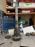
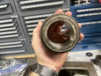
With the spindle out, you can get a better sense of how beefy it is!
image.jpeg
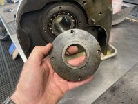
The bearing locking ring holds the front spindle bearings in place, and thus the front bearing retainer. As much as I would like to take the front bearing retainer off for painting, I think I am going to leave it on there. Those bearings are damn hard to come buy and if you can find them, they are extremely expensive. So probably best to leave it be.
image.jpeg
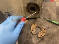
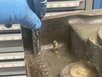
At the 6 o'clock position on the front bearing retainer plate, there is an oil drain. Mine was completely clogged full of crap. I got most of it out with a pick. Hopefully a good flushing will clean the rest of it out. If not, I might have to take the bearing assembly apart.
image.jpeg
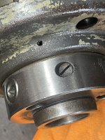
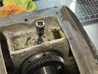
The 3 spindle lock cams, each have a detent screw associated with them. I removed the screws.
image.jpeg
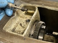
Then used a pick to pull out the detent spring behind each of them.
image.jpeg
I could then push the lock camps into the center of the spindle to remove.
image.jpeg
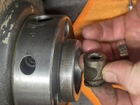
Followed by the detent plunger.
image.jpeg
I scraped the old gasket off of the front of the head stock. There is an oil return line at the 6 o'clock position. Its fully clogged as is going to take some effort to get it to flow again.
image.jpeg
I then removed the pipe cap on the head stock drain. Oiled flowed from it very slowly. Its probably clogged at 80%. While the oil was draining, I turned my attention to the front of the head stock.
image.jpeg
I removed the oil fill plugs, then started to work on the oil sight gauges. All of them are either missing the sight glass, or the sight glass is broken, so I will have to replace the glass.
image.jpeg
I was able to get one of them out using a splunger tool. You can see the cork gasket still in the bore. The cork has glued the other two in, so I'll need to try some solvent or heat on them.
 
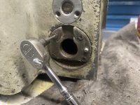
The mounting plate for the forward / reverse switch has for small screws holding it on.
image.jpeg
I had to clean the heads out with a dental pick, so I could get enough purchase with a hex socket to break them loose. They where quite stubborn.
image.jpeg
I then used a splunger tool to break the seal between the plate and the paper gasket behind it.
image.jpeg
Note, the small detent pin, and the detent spring behind it.
image.jpeg
The clutch shifter tube packing nut, is above, you can see some of the packing behind it.
image.jpeg
I removed it with my old camera spanner wrench... one of the straight attachments seem to have gotten lost in the top of my tool chest. I need to clean that out....
image.jpeg
The clutch shifter tube packing nut removed and the string packing that was behind it. I wonder if I could replace the sting packing with an oil seal?
image.jpeg
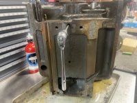
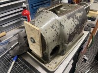
I then flipped the headstock on to its nose. With the spindle out, its still F'n heavy! The mounting brackets and their bolts get removed, so it will sit flat on the bench to work on it.
image.jpeg
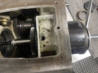
Note the two holes along the center line. They each have a set screw
image.jpeg
Followed by a Dog point set screw under them.
image.jpeg
I believe these secure the reverse idler studs.
 
image.jpeg
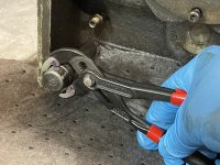
The ¼" x 3" pipe nipple was awfully tight. I ended up having to do the tighten it to loosen it trick before I could get it to budge. The bijour oil fitting next to it, has no numbers on it. I'll have to figure out what size it is before I order one. Id compare it to my saddle ones, but thats already back on the lathe. This unit doesn't not appear to have the metering screens in it either.
image.jpeg
After the headstock had been sitting on its nose for a while, the rear spindle bearing spacer slid out under its own weight.
image.jpeg
There is a factory mark "D" on the end opposite the bed.
image.jpeg
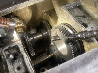
The spindle clutch gears are each held in place by a set screw.
image.jpeg
With a dog point set screw under it. Note the Left Hand (rear) spindle clutch gear has a longer dog point holding it in then the (front) Right Hand gear
image.jpeg
I placed a witness mark on it top center. It also has two factory dimple marks to indicate this as well. The left hand gear also has a "M" stamped on it.
image.jpeg
The Right Spindle clutch gear (front) has the shorter dog point screw.
image.jpeg
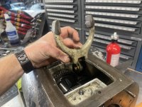
The spindle clutch fork is held in place by two SHCS that each have a lock washer under them.
image.jpeg
It has to come out to get the gears out.
image.jpeg
I then removed the set screw on the right hand reverse gear. That gear is located under the tachometer and I didnt want to risk breaking any gear teeth when I pressed out the Right (front) spindle clutch gear.
 
I'm not a fan of pounding to taping on bearings, when they can be pressed out. So in order to get the spindle clutch gears out, I needed to make a makeshift press.
image.jpeg
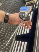
Some all thread and the plastic drifts out of a cheap seal press kit I had did the trick.
image.jpeg
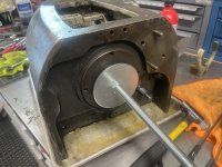
In order to help keep things aligned, and to prevent the press from binding or the all thread from hitting the machined surfaces I used smaller plastic drifts that fit into the bore.
image.jpeg
The other end I used a plate across the rear bearing retainer.
image.jpeg
The Right (front) spindle clutch gear pressed out very easily.
image.jpeg
image.jpeg
Note the factory alignment marks on the bed end.
image.jpeg
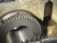
View from the front of the spindle toward the end-gear side.
image.jpeg
 
The rear spindle bearing retainer is hold on by 4 SHCS. With those removed I couldn't get it to budge.
image.jpeg
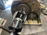
Luckily there was enough space between the bearing and the inner oil throw plate to get my Posilock internal bearing puller. A couple hits with the slide hammer attached and it came right off.
image.jpeg
image.jpeg
image.jpeg
Note the oil return passage just off of the 6 O'clock position.
image.jpeg

It corresponds to the channel as marked by this pipe cleaner. The oil throw plate channels the return oil into a groove in rear bearing retainer plate and then back to the return passage via this.
image.jpeg
I put a witness mark at top center on the bearing here.
image.jpeg
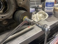
To remove the bearing, I used my shop made puller setup again, but this time with a section of 4" abs pipe as a bearing catching cup.
image.jpeg
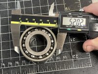
The bearing is a New Departure 5210. It's marked with an "r" and has a check mark on it along with "12XX" that looks like a factory scribe mark. Not idea what any of those designations mean. The bearing feels to be in good shape.
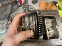
 
To get the Left Hand (rear) spindle clutch gear out, I first removed the set screws on both the Left hand reverse gear and the reverse idler gear to prevent from damaging any of the gear teeth.
image.jpeg
The reverse idler gear had a very long dog point set screw.
image.jpeg
The left hand reverse gear had a much shorter dog point.
image.jpeg
I then used the same puller setup as before, but this time with a piece of scrap ply over the nose end.
image.jpeg
image.jpeg
That gear took considerably more effort to press out than the front!
image.jpeg
image.jpeg
The bearing at first felt like it had an issue, but after playing with it a bit, I think the bearing / gear stack is way looser than the front, so I'll probably take it apart and see if I can adjust it.
 
View attachment 373994
The ¼" x 3" pipe nipple was awfully tight. I ended up having to do the tighten it to loosen it trick before I could get it to budge. The bijour oil fitting next to it, has no numbers on it. I'll have to figure out what size it is before I order one. Id compare it to my saddle ones, but thats already back on the lathe. This unit doesn't not appear to have the metering screens in it either. ...
I think that someone used a dead Bijur fitting to connect the overflow line to the headstock. Bijur fittings have a little valve that needs pressure (5 PSI? 15PSI?) to operate. It makes no sense to have one in that location. Check and see if the guts have been drilled out of the fitting.

Cal
 
I like this idea. I have not seen any imagery of the switch setup. Mind sharing a couple of pics / part number for the switch? Thanks!

I am not where I can take a pic at this moment, but if you want to copy the factory setup, you'll need to make a new plunger shaft which has a ring? bump to press on a button switch that mounts on the top of the plunger housing. I think you'll be able to modify the plunger housing also. I don't remember if I made a new shaft or not, but I think I did. I also bought a new switch, which was common and wasn't hard to find. Pics will follow when I get back to the shop.
 
I think that someone used a dead Bijur fitting to connect the overflow line to the headstock. Bijur fittings have a little valve that needs pressure (5 PSI? 15PSI?) to operate. It makes no sense to have one in that location. Check and see if the guts have been drilled out of the fitting.

Cal
Cal, it is missing all of its guts. So guess that makes sense as to why no numbers on it as it’s just acting as a compression fitting.
 
View attachment 373994
The ¼" x 3" pipe nipple was awfully tight. I ended up having to do the tighten it to loosen it trick before I could get it to budge. The bijour oil fitting next to it, has no numbers on it. I'll have to figure out what size it is before I order one. Id compare it to my saddle ones, but thats already back on the lathe. This unit doesn't not appear to have the metering screens in it either.
View attachment 373995
After the headstock had been sitting on its nose for a while, the rear spindle bearing spacer slid out under its own weight.
View attachment 373996
There is a factory mark "D" on the end opposite the bed.
View attachment 373997
The spindle clutch gears are each held in place by a set screw.
View attachment 373998
With a dog point set screw under it. Note the Left Hand (rear) spindle clutch gear has a longer dog point holding it in then the (front) Right Hand gear
View attachment 373999
I placed a witness mark on it top center. It also has two factory dimple marks to indicate this as well. The left hand gear also has a "M" stamped on it.
View attachment 374000
The Right Spindle clutch gear (front) has the shorter dog point screw.
View attachment 374001
The spindle clutch fork is held in place by two SHCS that each have a lock washer under them.
View attachment 374002
It has to come out to get the gears out.
View attachment 374003
I then removed the set screw on the right hand reverse gear. That gear is located under the tachometer and I didnt want to risk breaking any gear teeth when I pressed out the Right (front) spindle clutch gear.
Hey Grant, I know your rear spindle spacer slid out, but how loose was it? Mine is very loose. Any chance you could get dimensions of it for me?
 
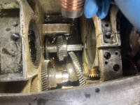
Up next is removal of the reverse shaft from the head stock.
image.jpeg
The rear bearing retainer for the reverse shaft was quite stuck. I ended up tapping it with a drift and a hammer to get it to rotate free.
image.jpeg
I could then pry it up free.
image.jpeg
It has a Victor 60250 oil seal in it.
image.jpeg
I used a blind bearing puller and a slide hammer to remove the oil seal as there was no way to push it out from behind.
image.jpeg
It's 44.5" OD, 1MM thick and the shaft is 25MM. Its not a common size. Based upon a post I found on PM, I ordered two of these. AVX #TC25x44.5x6.
image.jpeg
I had previously removed the setscrews from the reverse gears to get the clutch gears out.
image.jpeg
Using a long pry bar, I was able to slide the gears a bit on the shaft, but not easily. I suspect the woodruff keys for them may be burred.
image.jpeg
To protect the gears from the shaft pulling forces, I placed a piece of ½" scrap ply between the rear gear and the headstock housing, then placed another block of scrap hardwood between the two gears.

Based upon that same thread referenced above, I put together a puller to remove the rear bearing, the reverse shaft and both reverse gears.
image.jpeg
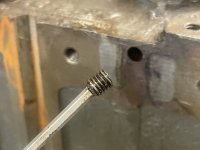
The reverse shaft end is ⅜-24 fine thread. Using a coupling nut and an extra ⅜-24 bolt that I had ordered for the tail stock I made a puller with some steel cups and tubing from a truck ball joint press kit I have.
image.jpeg
 
Top view of the setup
image.jpeg
It took quite a bit of force to pull the shaft and the bearing free. I think you would have a hell of a time doing it with a slide hammer setup.
image.jpeg
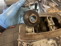
The RH (front) gear slid off pretty easily
image.jpeg
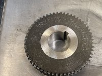
I marked it and the side facing the lathe's bed with a carbide scribe on a non wear section of it.
image.jpeg
I had to add some more tubing to the puller to get the LH (rear) gear off of the shafts woodruff keys. It was quite stubborn
image.jpeg
It also got marked with the carbide scribe
image.jpeg
The rear reverse bearing was a loose slip fit on the reverse shaft. Its a New Departure 5205D. its 52mm OD and 25MM ID X 20.57mm thick
image.jpeg
The Woodruff keys In the reverse shaft where quite stubborn to get moving.
image.jpeg
I ended up placing the shaft into my Starrett bench block to keep it steady so I could tap the woodruff keys out with a brass pin punch. I believe they are a size 4.
image.jpeg
I used a slide hammer and a blind bearing puller to remove the front bearing from the head stock casting.
image.jpeg
Its a New Departure 3204 bearing, but there is a 4 scratched in front of that number. I believe this signifies it has a snapping on it. Both of the reverse shaft bearings felt a bit chunky, so I ordered new-old stock replacements for them.
 
The rear spindle bearing retainer is hold on by 4 SHCS. With those removed I couldn't get it to budge.
View attachment 374012
Luckily there was enough space between the bearing and the inner oil throw plate to get my Posilock internal bearing puller. A couple hits with the slide hammer attached and it came right off.
View attachment 374013
View attachment 374014
View attachment 374015
Note the oil return passage just off of the 6 O'clock position.
View attachment 374016

It corresponds to the channel as marked by this pipe cleaner. The oil throw plate channels the return oil into a groove in rear bearing retainer plate and then back to the return passage via this.
View attachment 374017
I put a witness mark at top center on the bearing here.
View attachment 374018
To remove the bearing, I used my shop made puller setup again, but this time with a section of 4" abs pipe as a bearing catching cup.
View attachment 374019
The bearing is a New Departure 5210. It's marked with an "r" and has a check mark on it along with "12XX" that looks like a factory scribe mark. Not idea what any of those designations mean. The bearing feels to be in good shape.
Grant, when you pressed out the rear bearing, did you push on the inner or outer portion?
 
I have been following this thread, and all I could think was, Geez , I did all this too..and all this work kind of dimmed with age. Not to be sexist, but I suppose similar to giving birth, you don't remember the pain, just the result. I have a post talking about removal and replacement of that pesky front phenolic gear oil slinger bearing assy. with Rimcanyon, a few years ago. He didn't have a problem installing it, but I found I had to make an alignment fixture, so that the bearing was pressed in accurately ,otherwise the shifting shaft would bind. I think your headstock is similar.
 
Last edited:
Hers's a pic of the spindle lock switch setup. I think you can figure out how it works. You push in and twist the knob, and the setscrew rides in a groove in the shaft and holds it in. The switch button is actuated when you twist the shaft. I don't think there is any alteration of the shaft , he says... The switch is a Square D class 9007 A0-2. My original is Made in England of all things... crazy. IMG_0416.JPG


Back
Top